
The Relationship between Resistance, Voltage and Current
Resistance
I’m a metalhead so when I hear this term, I immediately think of a song from my favourite rock band, Skillet. If you are a normal person and do not like torturing your eardrums then you probably know what this term means. Resistance is going against the flow. Now let’s look for the proper definition of this term in electrical circuits.
Resistance is the measure of the opposition to current flow in an electrical circuit - https://www.fluke.com/en-us/learn/best-practices/measurement-basics/electricity/what-is-resistance
I forgot to mention a very important fact in the previous post. There are things called SI Units. This is a system of measurement that has units of measurement that are known across the whole world. Imagine if everyone had their own way of defining quantities. What we call 240 Volts (240V) may be called 240 Teslas (240T) or 240 Magic Waves (240MaWa). That is where the standard SI units come in. The SI unit of Resistance is the Ohm.
This means that the resistance of a device can be measured using Ohms.
Relationship Between Resistance, Voltage and Current
There exists a relationship between Voltage, Current and Resistance.
V = I R – that is what the Ohms law essentially states.
If we play around with the equation, it becomes:
R = V/I
and playing around with it even more gives us:
I = V/R
If you read our water example in the previous blog post, you know that the “tap” in that example represented the resistance. The more you open the tap, the more current that flows. The less you open the tap, the less current that flows. If you increase the resistance and keep the voltage constant, this will be like closing the tap more and more. If you do the opposite and decrease the resistance and keep the voltage constant, this will be like opening the tap more and more.
Voltage, Current and Resistance Measuring Instruments
Now, let us focus on something different for a moment. You know that Voltage exists, Current exists and Resistance exists but how do we measure them? How do you measure Voltage? How do you measure Current? What about Resistance? How do you measure resistance?
In order for you to do so you needed to use a meter which corresponds with the quantity.
For you to measure Voltage you needed a Voltmeter
For you to measure Current you needed an Ammeter
For you to measure Resistance you needed an Ohmmeter
Why not just measure Voltage, Current and Resistance with one device?
Well someone else thought of that a long time ago. That is where the Digital Multi-Meter comes in. It is a multi-meter because it can measure several quantities. A typical digital multimeter can measure resistance, current, voltage and more. Now that you know what this is let’s get back to what we were talking about.
As you probably know, when you draw an electrical circuit, you put in a “load.” I remember drawing a battery and a tiny box written load. The load could be a lamp, an electric motor, a heating element, etc. This load provides resistance to the flow of electricity. Electric circuits do not like operating without a load. When designing any circuit of any kind, you need to ensure that there is some sort of a load.
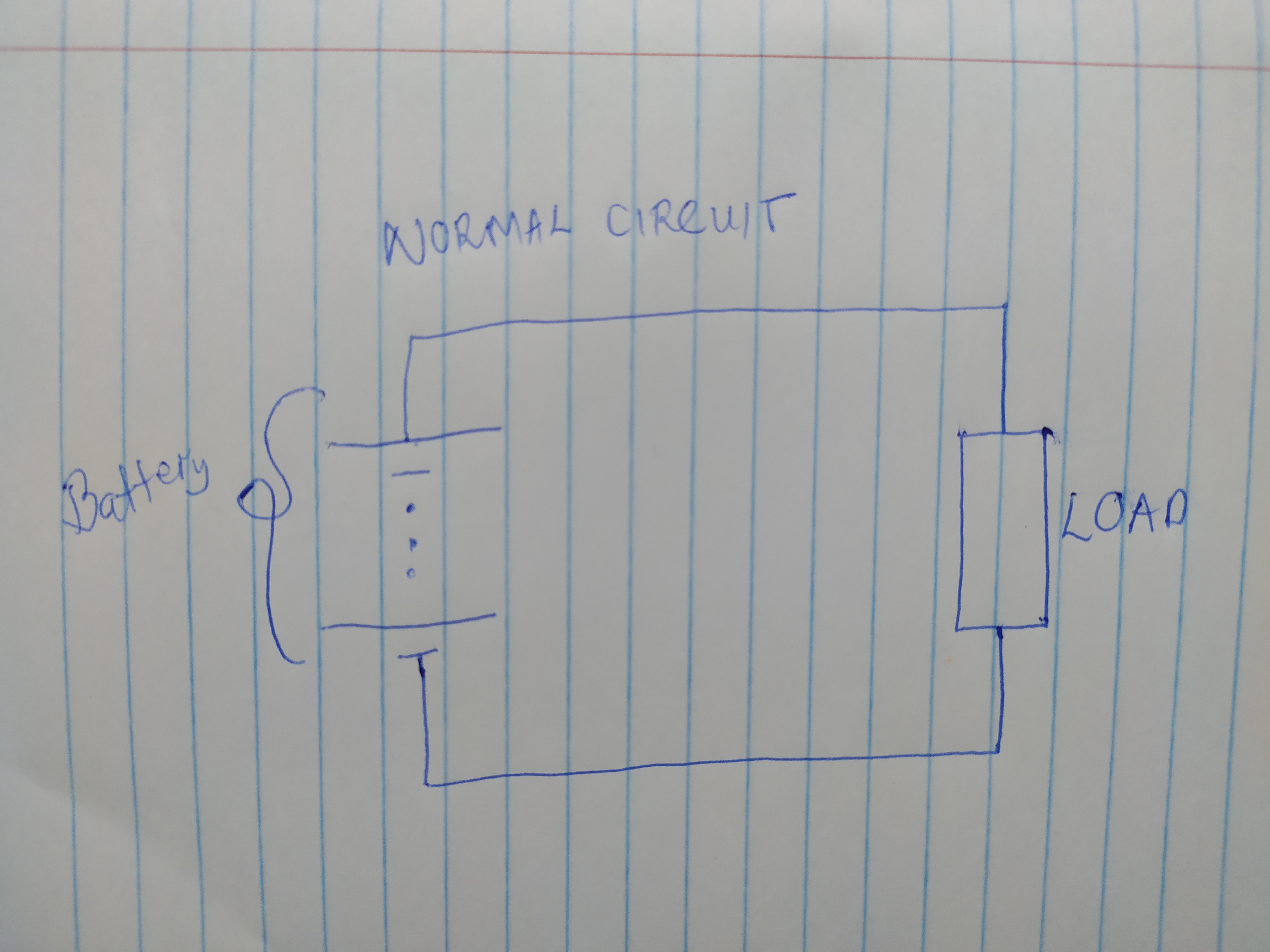
This is a normal circuit
Short Circuit
Now you may ask...What is a short circuit? Well, this is a circuit occurs when you have a circuit which does not have a load at all. If you were a naughty kid like me, you probably took a battery and shorted the terminals (connected a wire directly from the + to the -). There will be a magnificent spark and if you keep the terminals shorted, the battery could leak, explode or do something else that’s nasty. In electrical circuits, when there is a short that is when you have a magnificent explosion and you run away because while it is a magnificent sight, the sound is terrifying. Its also really dangerous. When a short circuit occurs, a very large current flows and this is what causes the rapid heating.
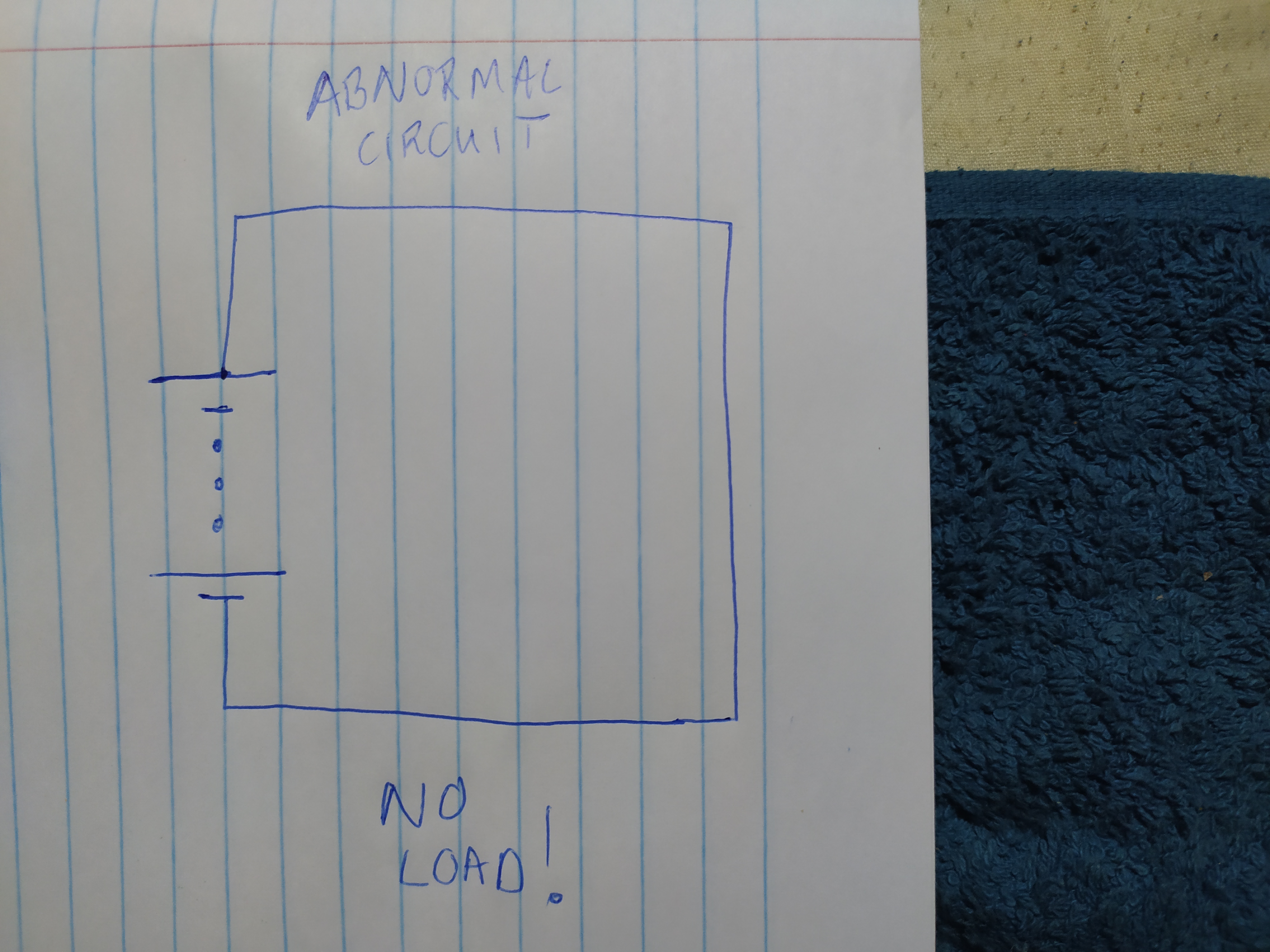
This is a short circuit diagram
What is an Open Circuit?
This is pretty much the opposite of a short circuit. In this scenario, there will be a circuit that has no current flowing through it at all. This will because the circuit will not be complete and this is often due to either a switch being present which creates an open circuit when the circuit is turned off or a faulty circuit e.g. a circuit with a blown fuse.
Open Circuit Example
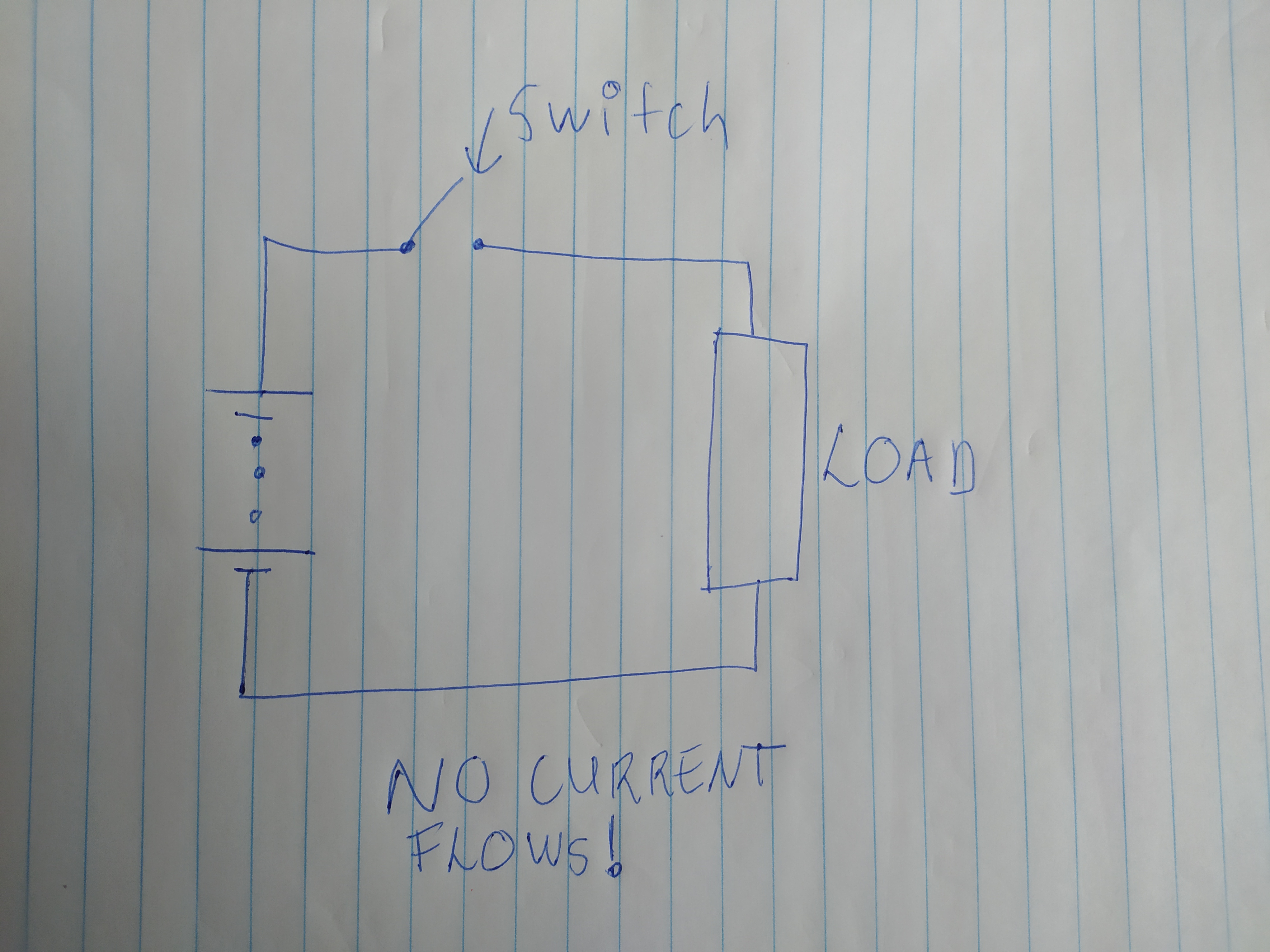
This is an open circuit diagram
Safety
Geniuses that existed before we were born realized that electrical devices malfunction and make short circuits and there is a need to help keep our houses from burning down. That is what made them invent safety devices such as fuses. A fuse protects the device from damage, and in older houses, there were fuses used in the main power board. That is why when you open up any square plug, you see that there is a fuse. Some electronic components even have fuses inside them. These fuses conduct electricity just like a normal wire but blow out when current above a specific value flows through them.
Its Practical Time!
Now that I’ve loaded you with a lot of knowledge, time to see where this knowledge actually works. Let’s say you have a fuse which has blown out. Your simple solution is to replace the fuse. This isn’t too hard. You open up the plug and remove the fuse. Coincidentally, both the fuse inside and the fuse to be replaced are of the same brand and they both look identical. What do you do?
You could manually put them into the plug and see what works. Or you could use a digital multimeter.
As we mentioned earlier, a fuse is a special wire that conducts electricity and melts/blows out when the current goes over a certain value.
You can use the multimeter to measure its resistance. Since it is a simple piece of wire that conducts electricity as long as the current is below a certain value, the resistance must be very low. 1-3 Ohms is a very fair value to get. Ideally we would want to get 0 Ohms, but this is not possible because wires have their own resistance.
So you you simply use the digital multimeter to measure the resistance of both fuses. The one with a very large resistance is the dead one. The one with a very low resistance is the one that still works.
Scenario #2
You have a cordless kettle. The fuse got blown. You replaced it. You connected it to mains AC and BOOM! Another explosion. The questions present are now:
Is the kettle dead? or
Is the base of the kettle dead? or
Is the cable dead?
Before calling the electrician and getting charged a ridiculous amount of money that will be enough to buy 2 goats and a dead cow, try diagnosing it yourself. Remove it from Mains AC. Remove the kettle from the base. Open up the plug. Check the resistance between Live and Neutral pins. If it is a very high number then that’s good. The live and neutral wires should never meet so the resistance must be high.
If its a very low number, near zero then you have a problem – most probably a short circuit. This probably means that the kettle is not dead. Its either the base or the cable. Performing a visual inspection of the wire can reveal problems. Maybe there is a cable made in two parts and where they are connected there is a noticeable problem. Maybe there’s a part that’s burnt.
Try using another person’s base. If it works then your kettle is probably OK. All you need to do is get yourself a new base. You could repair it yourself, but I won’t really recommend it since you may not know how to fix it even if you identified the problem.
Just like that you’ve avoided spending money enough to buy goats on something that your electrician will pretend to struggle with so that it appears that he did hard work.
Conclusion
And that’s it for this week. In the next blog post, we will learn how to check if a circuit is overloaded. The next blog post will be around 14 October.


Comments