Component Series: The Introduction
Welcome to this new exciting series! In this series, I will explain the basic components that are used in everyday consumer electronics gadgets. Let’s get started.
Basic Terms You Need to Know
- Motherboard – This is the place where all the components are placed.
- Active Component – this is basically, an electronic component that supplies energy to a circuit.
- Passive Component – this is an electronic component that only receives energy in the electrical circuit.
The Motherboard
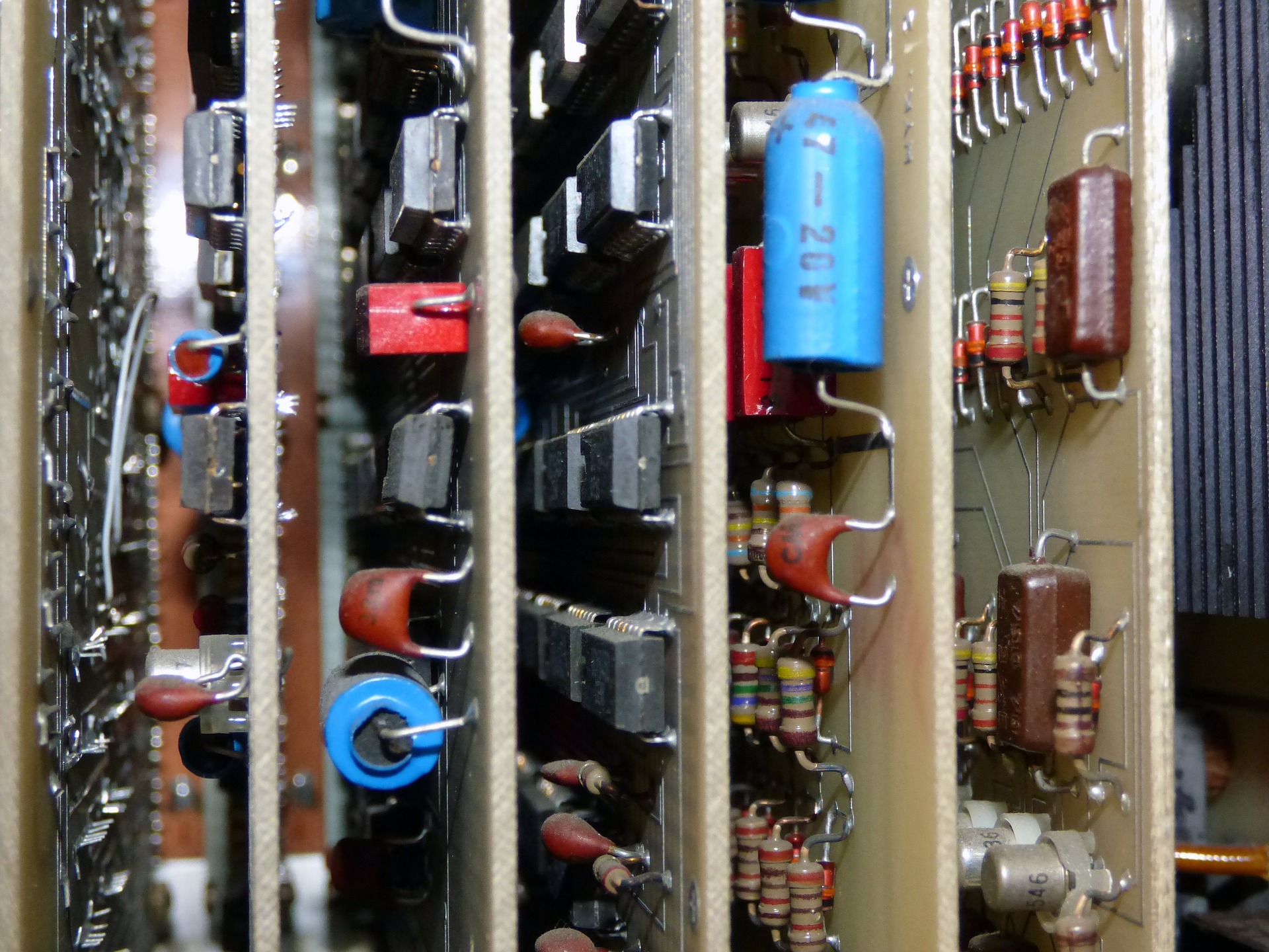
Have you ever opened a dead electronics gadget? Or have you seen a dead electronics gadget being opened? If you have, then you might have seen a green or brown board with several strange things that are black, orange, and brown in color. You might have noticed that there are some components that have several “legs.” Well, I’m going to explain what all those things are and what their functions are in electronics circuits.
Passive and Active Components
If you have opened a dead electronics gadget, you’ve probably seen the motherboard. On the mother board are several components. As mentioned above, some components have “legs” and look like strange millipedes (most of these are Integrated Circuits). Others look like tiny pieces of dirt and others just look like items from a mad scientist’s drawer.
All these individual components are either active or passive. When creating an electronics circuit, it is quite useful to know which devices are active components and which are passive. This is because the passive components behave in a completely different manner from the active components.
To read more about the similarities and differences between the two types of components, head over to this site:
https://circuitglobe.com/difference-between-active-and-passive-components.html
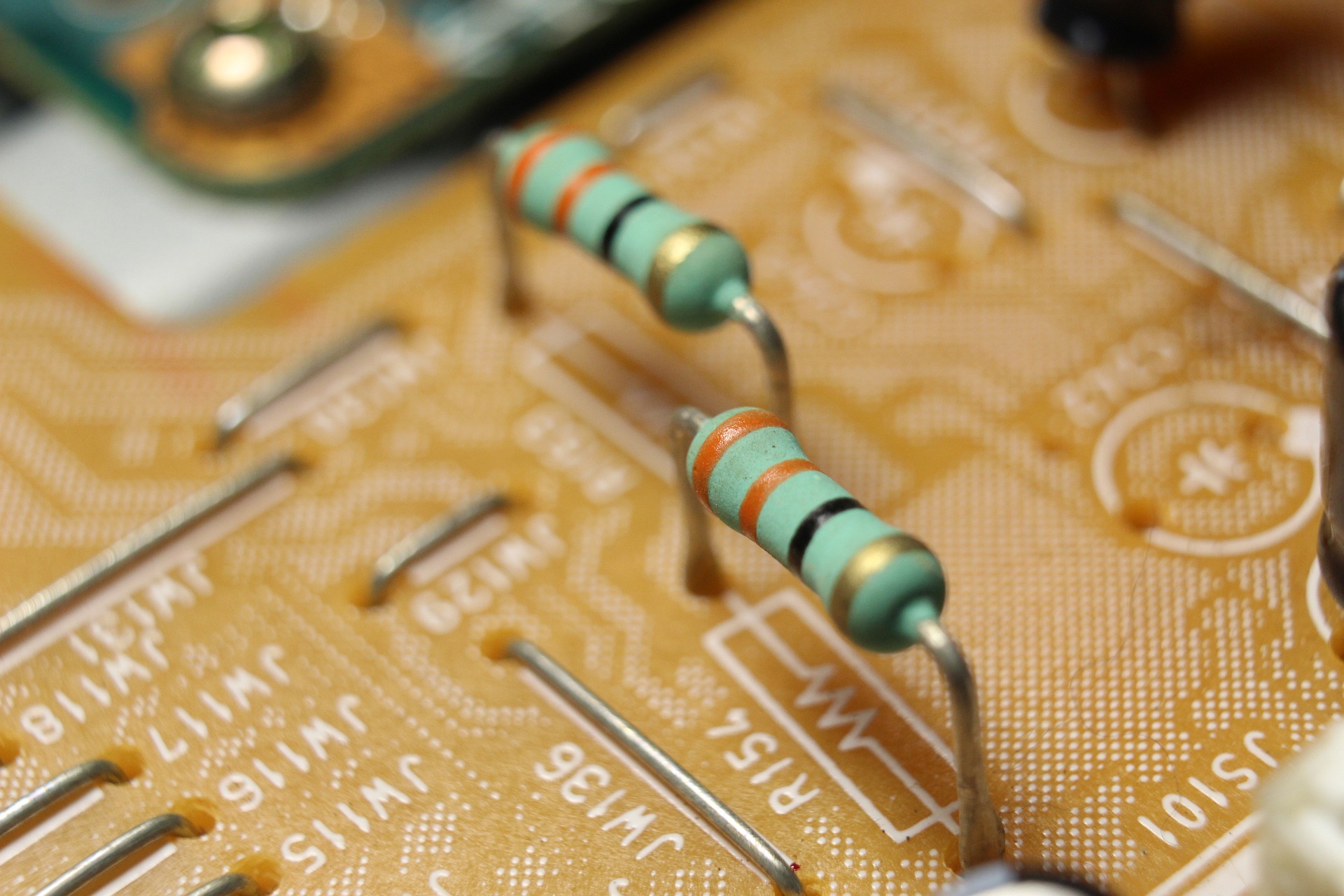
Resistor
This is a device that looks something like this

This device works in a very simple manner. As the name suggests, its function is to resist – in this case it resists the flow of current. It is put in electronic and electrical circuits to control the amount of current that flow through the electronic or electrical device.
If you read the previous blogpost, you probably remember the equation we used: R=V/I
Playing around with this equation gives us I = V/R. This therefore means that to allow a specified amount of current to flow in an electronic device, you need to choose a resistor that goes hand in hand with the particular voltage present.
Example
If I want a current of around 0.01A in a 5V circuit, I would want to have a resistor with a value of 5/0.01 = 500 Ohms.
Why Do We Need Resistors?
We need resistors to limit the amount of current that flows in the electronic circuit. Why do we need to limit the current? Well, in electronic circuits, there are several components that are present that are sensitive to the amount of current present. If there is more current than the device was made to withstand, it will fail.
What is the Color Code?
That is a good question. Electronic components are rather tiny and there needs to be a way to identify what the component is and what its value is. Ordinary resistors have their distinct shape so one can identify them by just looking at them. To get the value, you need to read the color code. I could write a full blog about this, but I feel that this guy did a better job. Head over to this blogpost to learn more about resistor color codes. Don’t forget to come back when you’re done!
https://eepower.com/resistor-guide/resistor-standards-and-codes/resistor-color-code
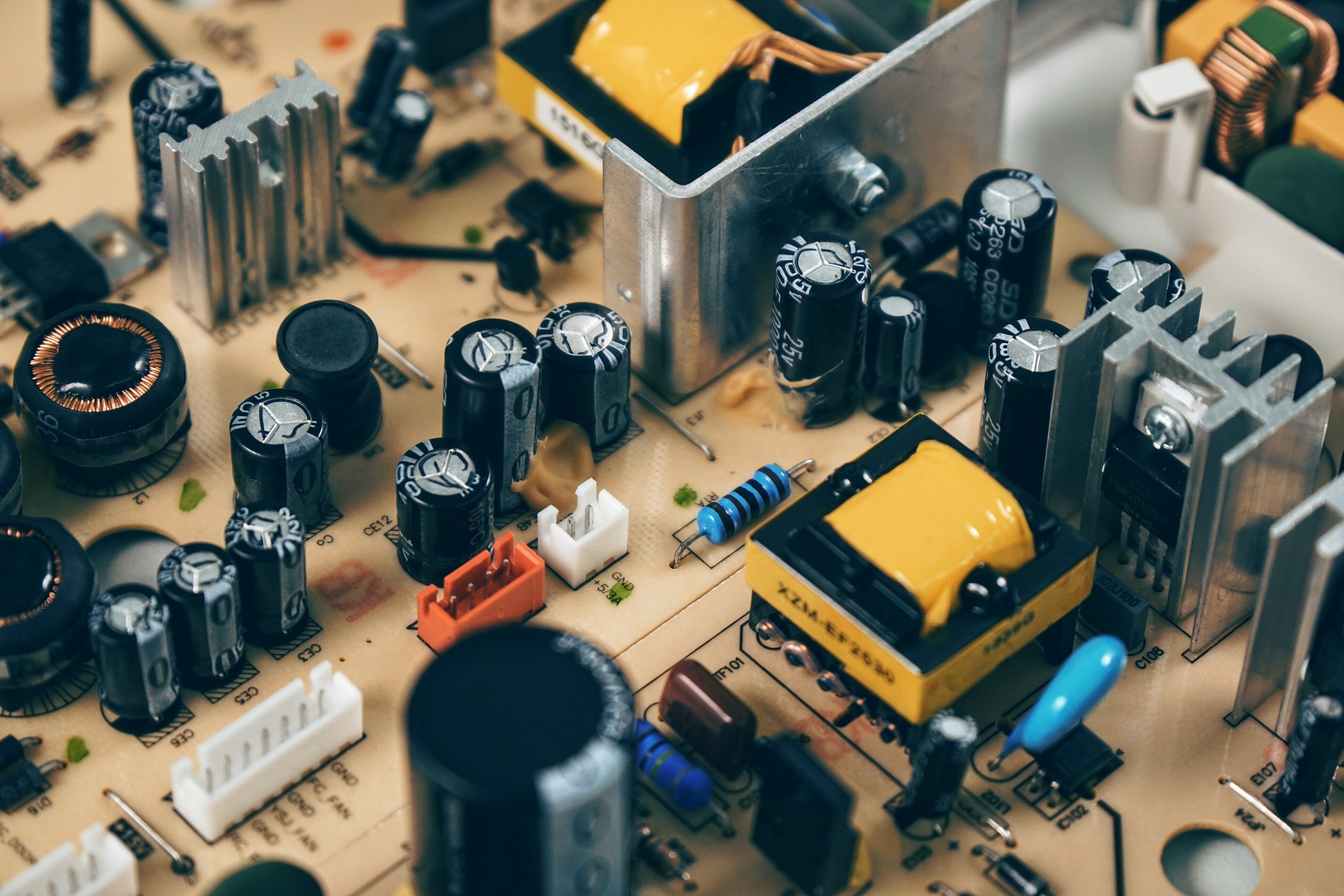
Capacitor
This is a device that looks something like this:
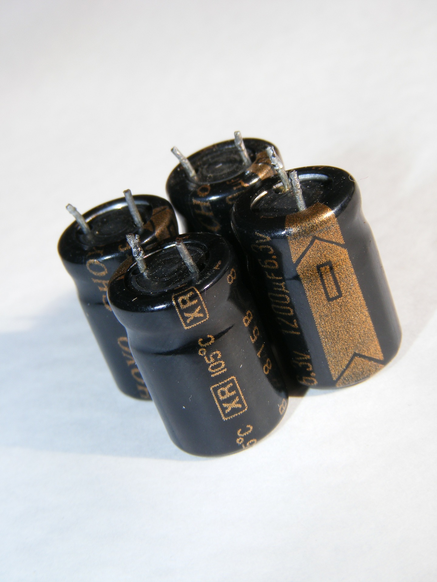
These devices are used quite often in electronics circuits. These devices are present to store energy in the form of an electric field. This energy is then used when the power supply is removed. The energy is discharged and used in the circuit.
Let us have an example to explain how this works.
Say we have an AC signal. We want the AC signal to be converted to a DC signal. To do so, we use special electronic components called diodes (don’t worry, I’ll mention these later in the series). The AC signal is then rectified into a DC Signal.
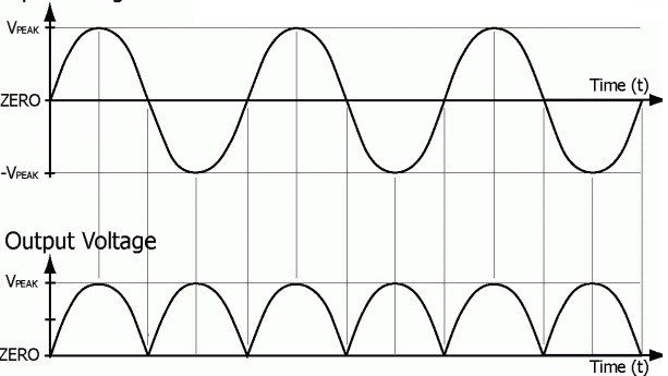
Image sourced from Watelectronics.com
As you can see, the DC signal is not smooth. In fact, it does not look like a DC signal at all. It looks like a strange looking AC signal. Some devices are not able to use such signals and need a proper DC signal. To achieve this, we use a capacitor. The capacitor gets charged when the wave form moves to the maximum value. When the wave form starts to move down from the maximum value, the capacitor discharges. The waveform that results is nice and smooth as shown below.
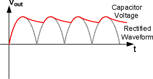
Image sourced from electronicsforu.com
Inductor
This is a device that looks something like this:
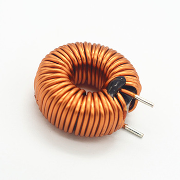
These devices aren’t as popular as resistors and capacitors. Like capacitors, they store energy in an electronic circuit but the difference between inductors and capacitors lies in how the inductors store energy. They store the energy in the form of a magnetic field. This energy is then used when the power supply is removed. The energy is discharged and used in the circuit.
The Golden 3
I call Resistors, Capacitors and Inductors the Golden 3 because most electronic circuits, and the basic principles behind the complex components use the basic principles used by resistors, capacitors and inductors.
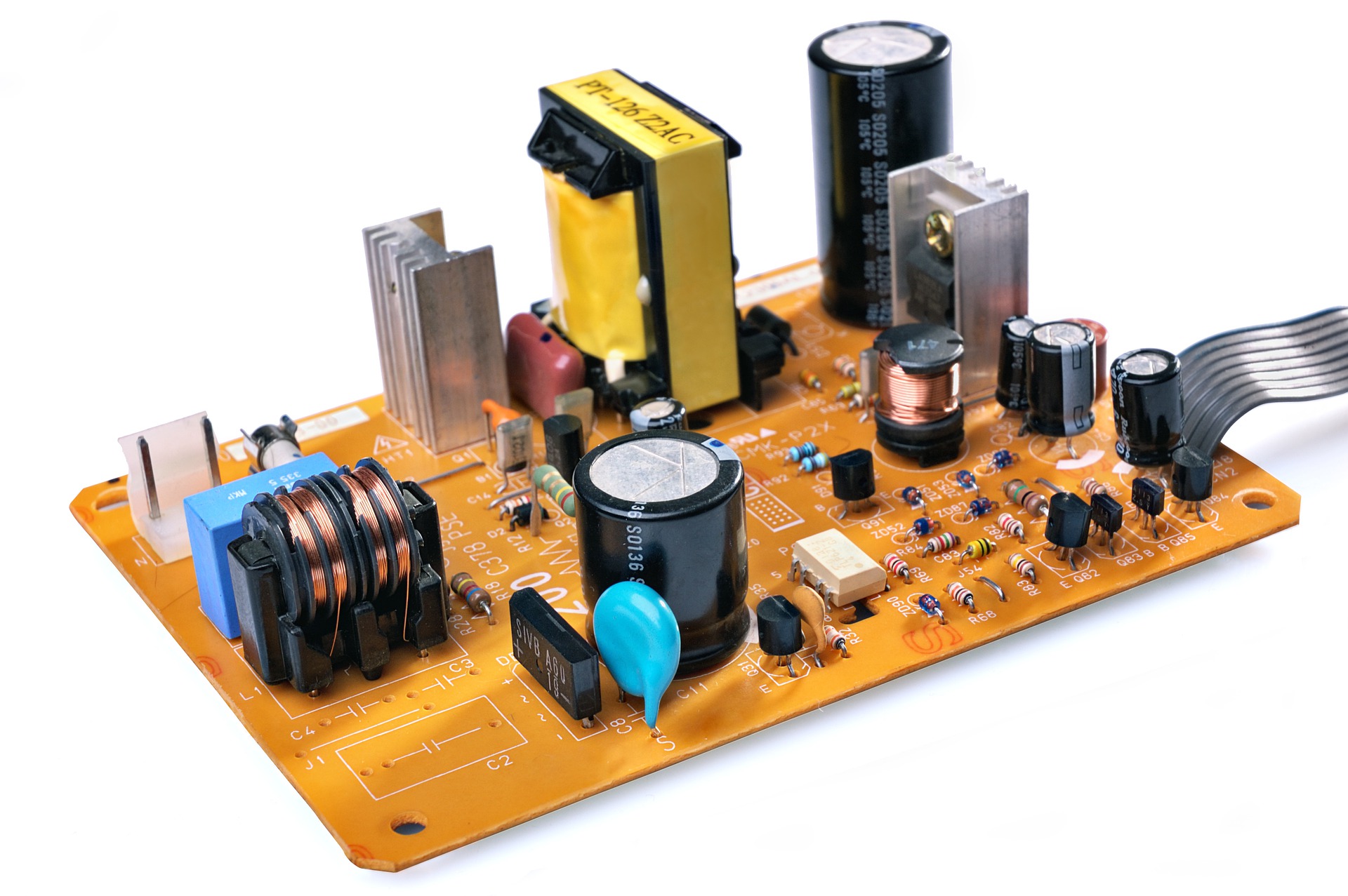
Practical Moment
This is going to be a rather easy task for you to do. Try to find diagram of motherboards on the internet and identify the resistors, capacitors and inductors present.
In the next few sessions, the practical sessions will get more interesting as we will open stuff up : ) Stay tuned!


Comments